Boscastle Locomotive Limited
16th May 2014
Valve Liners
We still await the services of Bryn Engineering to fit and bore the valve liners as described in the last newsletter. The latest is that the boring equipment has been delivered for a start next Monday.
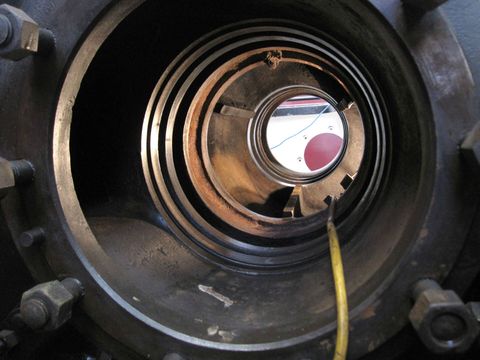
This is a view up the valve bore, looking from behind towards the front of the loco. The four circular ribs at each end of the valve bore need to be machined to remove slight ovality before the new valve liners can be machined and fitted.
In this picture we see the front of the loco with the middle cylinder and the valve bore above it. This might help those not familiar with the mechanics of the loco by illustrating where the valve bore is.

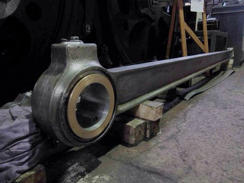
Coupling & Connecting Rods
These require only the final skim to size of the white metal before fitting. This depends on the availability of a precious resource - Craig Stinchcombe, who has several calls on his time.
Once these have been machined, Andy has to tackle the task of turning the driving wheels to the same absolute position, so that the bearing pin spacings match the coupling rod pitch.
Fitting these will be a very visible step forwards and a significant boost to morale.
Boiler
Andy Morgan and Mike Playle have an appointment with the boiler shop foreman at Crewe on Friday to consult on procedural, legislative and engineering processes associated with a major boiler repair.
Hopefully this will equip us to draft a repair plan and gauge scope, resource requirement and cost.
We have had an offer of help from a qualified welder. Although he is still in full-time employment, he will be able to assist with smaller tasks and vetting weld procedures.

8th April 2014
Refurbished components fitted back into the cab. The reverser can be seen on the right with its brass lamp. Under the driver's seat is the AWS relay box and to the right of that is the drain cock operating lever.
Some of the parts fitted to the cab roof above the driver can be seen. At the top can be seen a bell and horn, which are part of the Automatic Warning System (AWS). If a distant signal is at caution the horn will sound, and if not cancelled by the driver the brakes will be applied automatically. If the signal is clear (green) the bell will sound. There are plans to install this on the GCR in the future.

16th April 2014
This shows part of the underside of the tender front. This is not a photo taken at Barry scrapyard but one showing the effects of twenty-four years of preservation use. The tender was originally overhauled in 1990 for use with 35005 'Canadian Pacific'. We have started work to overhaul the tender once again.

17th April 2014
The refurbished tender draw-gear which forms part of the connection to the loco. The piles of rectangular steel and rubber form a pad through which the large pin on the end of the bench passes and is fastened with a large bronze nut. The rubber has a cushioning effect when the locomotive is pulling a train.
8th May 2014
All of the brake gear has been removed from the tender and shown here is the brake crossbeams with new end sleeves fitted. The new sleeves were heated (until bright orange), dropped onto the end of the beam, and then allowed to cool and shrink to a tight fit.

8th May 2014
The tender brake hangers have been removed, some easily, others taking several attempts by heating and hammering to remove the foot-long pins holding them on. A start has been made on re-bushing the hangers and converting them to grease lubrication to lessen wear and ease removal in the future.

8th May 2014
This shows the front end of the new right-hand valve spindle with the original front valve head in position. The valve head has been cleaned, ready for measuring for new valve rings which fit in the four grooves in the head and form a steam-tight seal. The end of the spindle slides in bushes similar to those shown above.

Images on this page are copyright A.J.Morgan, M.Playle