21st February 2014
Funding Boscastle Boiler Repairs
by Mike Playle
With Boscastle’s boiler now in the yard, steps have been taken to clean accessible areas of the firebox and undertake some non-destructive examination of areas known to give trouble in boilers of this construction.
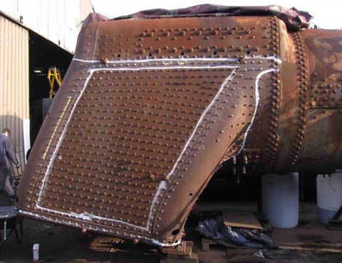
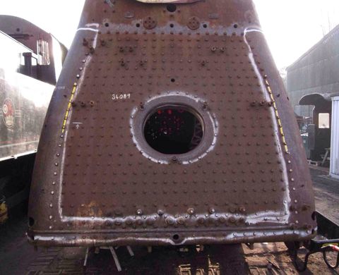
Peering through the firebox door, a number of areas can be seen to be cross-hatched in white, which indicate areas of plate to be removed and replaced entirely. Marks in yellow identify cracks determined by the NDT as emanating from the (currently non accessible) water side. Sections around these will also have to be cut out and replaced. Costs for this process have not yet been identified but coded welders do not come cheap.
Other items to be replaced include the smoke tubes and superheater flues (which run the length of the boiler water space), superheater elements and a large number of firebox stays. As and when the costs for these items are determined there will be opportunities for supporters to sponsor the various items.
We are starting with the mild steel stays as these are straightforward to identify and understand. We estimate that the minimum number we will need to replace is in the order of 1100.
The stays are threaded at each end with a good old fashioned Whitworth thread form at 11 threads per inch, and are typically 7/8” diameter. The two threads must retain their pitch exactly, despite the missing bit in the middle, because they must engage with the female thread in the inner and outer firebox sheets which are some distance apart. This also requires the thread to be cut (tapped) in the plates with no pitch error over the distance.
Each stay has to be removed by laborious processes but with great care so as to avoid excessive damage to the tapped hole. First the riveted heads are “ground off” to reveal the true centre of the stay beneath what might have been a lopsided head. What is revealed, however, is not the true centre, as we are looking at a cross section through a helical thread, so allowance has to be made for this.
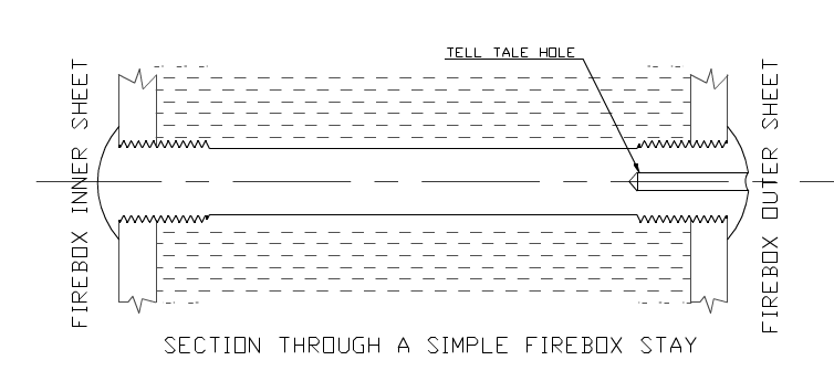
The stay then has to be drilled carefully so that, ideally, the screw thread in the plate remains intact and just a helical wire remnant of the stay remains to be winkled out. This is almost impossible to achieve without some damage to the inside thread so the next stay to be fitted is made a 1/16” or 1/8” bigger, but the thread remains at the same pitch. It is modern practice to provide a tell-tale hole on the outside of the stay to provide early indication of stay fracture. This would provide a useful centring feature for drilling, but I have not observed such a thing on Boscastle.
This photo shows a trial in my garage workshop on a sample, using my lathe as a drilling machine (my pillar drill only goes up to 13 mm). The helical wire remnant can be seen, before I winkled it out with scriber and pliers.
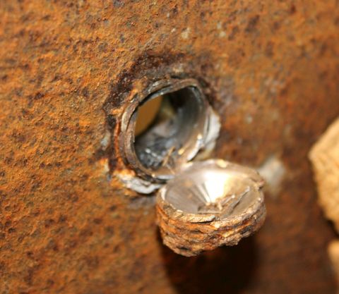
Of course, a complete stay would not fold aside like this cut-off fragment in my sample. Timing was three minutes for a pilot hole and ten minutes for the full size drill. The 19mm HSS drill started freshly ground but needed grinding again about two-thirds through. Hardness tests on the boiler plate and stay material indicated that they were both mild steel of similar strength.
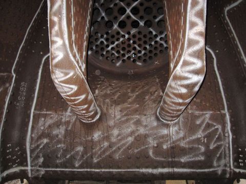
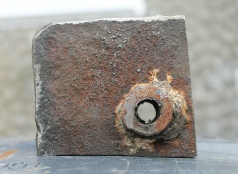
By way of a trial, I did engage a spark erosion specialist - who supplies broken tap eroders - to erode through a stay, but the results were not too convincing and a dedicated machine would be too costly. The advantages of spark erosion are that it is fast and also non-contact hence there is no risk of the cutting electrode being diverted and it is straightforward to run a second cut with an offset correction. Try doing that with a drill! Timing for this hole (pictured left) was four minutes with a smaller machine than we would normally use.
So how do we engage supporters with stay replacement? Firstly, if you have trade skills and patience you could sign up for some drilling and tapping. If you lack the time or inclination to contribute practically, then how about sponsoring one stay a week at £5 per stay? This roughly equates to the cost of a pensioner’s lunch at one of my favoured Leicestershire pubs. Donating this way via the David Clarke Railway Trust would buy five stays for the price of four if Gift Aid is applied. Sixteen donors signing up like this would pay for all of the steel stays within one year! We do also have to replace monel and flexible stays which have not been costed yet, but will be a lot more, so if you dine more extravagantly than me, please consider sponsoring some of these.
23rd January 2014
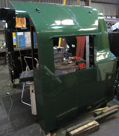
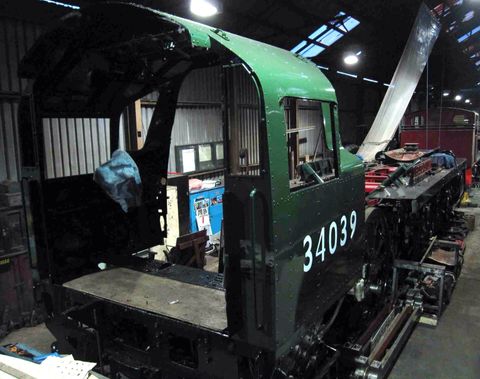
Shows the completed cab structure, in a freshly painted coat of green, sitting behind the locomotive.
24th January 2014
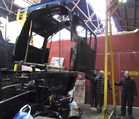
The cab is hoisted aloft using the shed's manual lifting gantry. Once the cab was lifted high enough, the gantry was rolled gently forward over the rear of the loco and the cab carefully lowered into position. Halfway through the operation and posed for a team photo are, from left to right, Nigel Tilly, Keith Devereux and Malcolm Prosser.
13th February 2014
The cab now sitting on the rear of the loco, fastened to the under-frame. Many overhauled parts have been re-fitted having been left off to reduce weight during the lifting process. Despite its size, the cab structure is relatively flimsy compared to a lot of locomotives and great care was taken to avoid damaging it.
13th December 2013
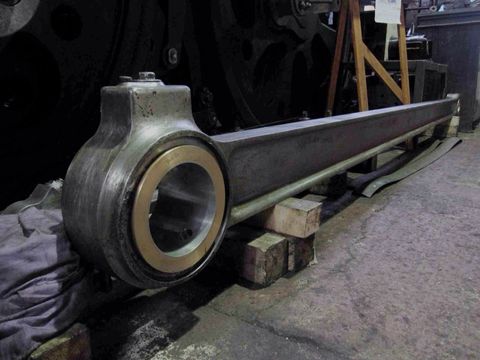
This shows the right-hand connecting rod with the new big end bearing fitted. This has been pressed into the end of the rod using the sheds hydraulic press, eight tons of force being required to push it in.
19th December 2013
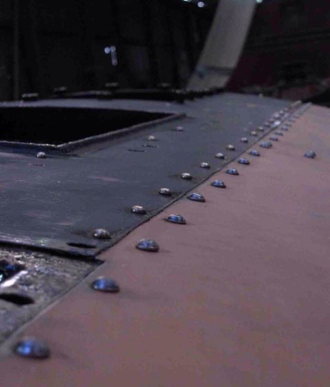
Some of the 600 copper rivets that fasten the steel sheeting to the cab frame. All of these were machined and supplied free of charge by a friend of Keith Devereux, one of our regular volunteers. Keith and his boss, Arran, also supplied all of the new steel for the cab at no cost to BLL. A big thanks to them from all concerned.
4th February 2014
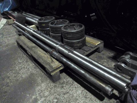
A new valve spindle for the right-hand cylinder sitting on top of two original valve spindles. This was machined by our volunteer turner, John Fletcher, with key and cotter slots put in by volunteer machinist Ken King. Some careful setting was required to ensure this item remained straight as only half of the rod could be machined at any one time, none of the lathes in the machine shop being long enough to machine the whole rod in one go. The other valve spindles have been skimmed and polished to restore worn surfaces.
12th February 2014
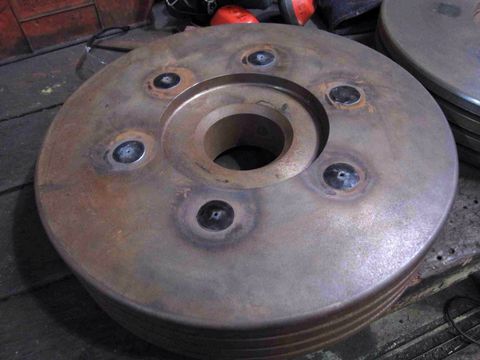
Shown here is one of the new piston heads with six core plugs filling holes formed in the casting process. The holes are tapped and countersunk on both sides and then the plugs are screwed in. The heads of the plugs are heated and caulked (hammered) to spread the edges into the countersunk ends. This ensures that the plug cannot come out, as if this should happen while the loco is working the results would be catastrophic, with broken cylinder covers at best, or smashed cylinders at worst!
13th February 2014
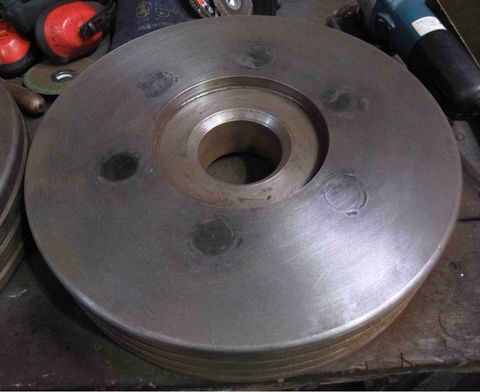
A finished piston head with core plug ends polished flat. There is very little clearance between the end of the cylinder and the piston head, so it is important that nothing protrudes from the face of the piston.
Images on this page are copyright A.J.Morgan, M.Playle