Boscastle Locomotive Limited
26 February 2016
Boiler Work and South Devon Quotation
We are now in receipt of a quotation from the South Devon Railway for a new inner firebox and some other boiler work. There are a number of points in the quotation which need to be clarified, but in essence we now have a much clearer indication of the level of fund raising which we will be facing. This work is of high priority and we are actively looking into how we need to address this major task.
If other Bulleid owners are able to place similar orders there is a definite opportunity for cost savings to be made on materials. To this end we are in discussion with two other Bulleid owners.
Work Started On Assembling Valve Gear
It must now be more than two years ago that I took on the challenge of recovering the distorted expansion links so I was quite excited when the time came in January to fit the outer valve motions to the locomotive as the culmination of that process.
In preparation for this the volunteer team had spent some time putting a shine on the steel surfaces and Andy and Ken had completed the machining of the die blocks with a labyrinth of oil ways. Andy’s photos should show how visually impressive these parts appear.
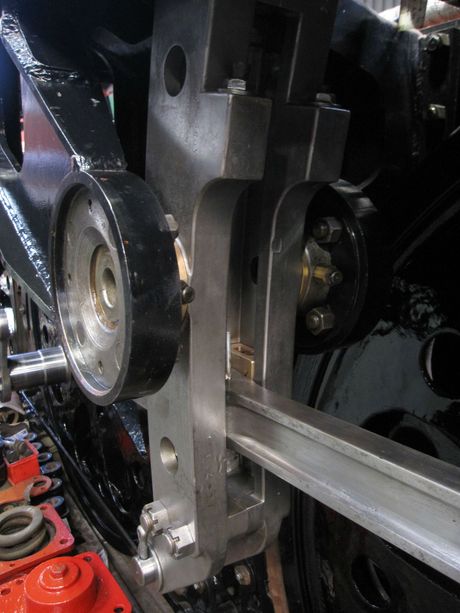
Prior to offering the parts up all the grease galleries and reservoirs were filled from a grease gun to displace any swarf. Starting on the left side of the locomotive the first parts on were the bearing bushes for the expansion link trunnions, the outside bush being left loose to provide a bit of space. The inner half of the expansion link was offered up, then the outer half and this then rotated to meet the inner and the four fitted bolts inserted to make the two halves one rigid assembly. The bolts holding the bushes were tightened and we indulged ourselves by swinging the expansion links to and fro imagining the time when the eccentric rod would provide that motion.
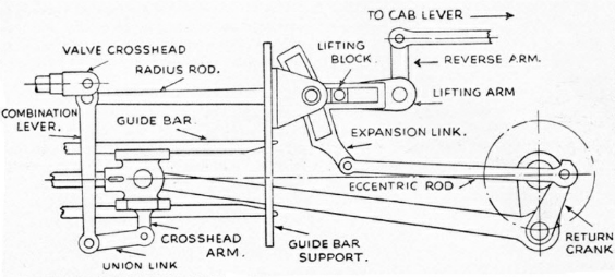
Then followed the radius rod, fitted initially without its bronze lifting block so that we could judge the freedom of the expansion link die blocks. These vital parts are unfortunately not shown in the diagram – but connect the radius rod to the curved track of the expansion link. The die blocks, once connected to the radius rod, slid freely from top to bottom of travel thus proving the accuracy and effectiveness of the recovery much to our relief.
Fitting the lifting block, combination lever and union link followed without any problems.
Attention was then transferred to the right side of the locomotive. This was not to be so straight forward. The first hint of trouble was the reluctance of the fitted bolts, joining the inner and outer halves of the expansion links, to pass cleanly through. Once persuaded into position the expansion links were very stiff to turn indicating a misalignment somewhere. The fitted bolts were knocked out, the outer bearing loosened and the heavy components lifted down.
Examination of the bearing bushes showed marking in the inner bush from high pressure contact. These marks were duly scraped out to remove a small amount of material. The expansion links were lifted back into place. With all bolts tightened the expansion links were no easier to move. After three trial assemblies with no sign of improvement it was concluded that there must be a significant misalignment somewhere.

We were confident that the expansion link trunnions were in line as this had been a starting point in our reworking of the parts. Investigation commenced with the bearing bushes bolted into place without the expansion links and a rule laid through across the two.
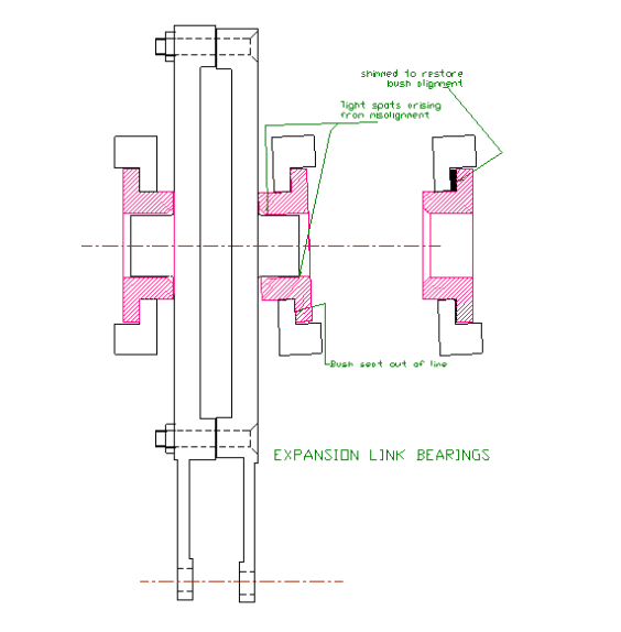
At one point of the circumference it was possible to see a gap between rule and bush. Measurements with feelers in this gap indicated that the axis of the inner bush was significantly misaligned to the outer. This misalignment was arising from the seating face being angled so that, when the bolts were tight the bushes were way out of line. Scaled to the pitch circle of the bearing fixing bolts one side of the bearing needed to be raised by 0.024”.
Shims were prepared and inserted to achieve this angular correction and the expansion links once more offered up. This time it swung freely and allowed us to complete the assembly process as per the left side with no further issues.
It is interesting to speculate how the misalignment came about and how previous assemblers had coped with it. The errant component is a heavy fabricated bracket fitted by BR during the 1950s “rebuild”. It should not have been difficult to machine this to “thou” accuracy as a stand alone component on the machine tools available at that time. How they managed to inject such a large “out of parallel” such as we have revealed here is a mystery to me.
There being no record of shims being revealed when the locomotive was last stripped I guess that the fitters at Eastleigh during rebuild either opened out bush to trunnion clearances to allow free rotation or left things tight to wear in with use, and ignored the root cause. It is unlikely that we will ever know, but comforting to know that, for this build, we have applied a solution that allows free movement with the design clearances.
Stones Generator
One of Oliver Bulleid’s innovations on his locomotive designs was the use of electricity for lighting. The generator currently fitted to Boscastle is a 100 psi single stage steam driven impulse turbine driving an AC generator rated at 500 watts delivering at 32 volts AC. The frequency of the AC is not stated in the available documentation but this does give a warning that any measuring instrument used should be rated to accept 1000Hz.
An opportunity has arisen to acquire a second electrical generator with a complete speed governor. This is a welcome development as it was looking likely that we would have to manufacture these missing components before returning ours to service.
Having transferred the missing parts over to our original it was considered sensible to trial run it. Using shop air at 95 psi we have measured 19 volts while lighting a single lamp. The rotational speed to achieve this was considerable, noisy and slightly unnerving. It is likely that the generator will run better with less viscous oil so more trials will be run in due course.
13th January 2016
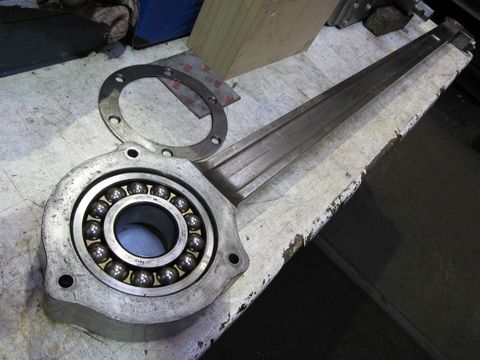
The left hand return crank rod has received a lot of polishing to remove corrosion marks, as has the rest of the valve gear. This rod is one of the very few items on the loco fitted with ball bearings and will be one of the last motion parts fitted. Thanks must go to Keith, Nigel and Malcolm for all the effort they have put into making these parts look almost as good as new!
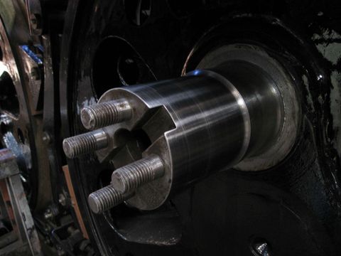
20th January 2016
This shows the polished right hand middle crank pin, big end journal. The process is laborious, taking about a day to complete each pin but the results are very good. All pin diameters are now accurate to within one to two thousandths of an inch and some even better than that! This work will allow improved clearances to be incorporated into the coupling rod bearings when final machining is done.
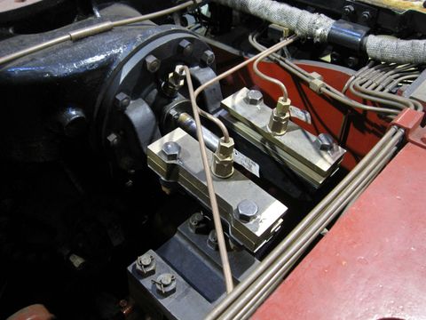
18th February 2016
The refurbished mid cylinder valve cross-head slides have been trial fitted to their brackets on the rear valve end cover. The lubrication pipework to the slides has also been finished, which leaves only two small pipes to make before all of the loco’s lubrication system is complete.
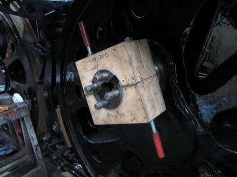
20th January 2016
The photo shows the middle crank pin, big end journal being polished. The crank pins were unevenly worn, so to help improve the fit of the coupling and connecting rods three polishing blocks were made to accommodate the three nominal pin sizes. Emery cloth is sandwiched between the block halves and clamped to the crank pin, the assembly is then rotated to polish off high spots to give a uniform diameter and smooth surface finish.
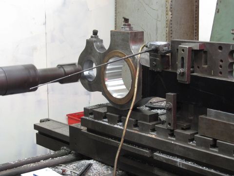
5th February 2016
At last, machining work has started on the coupling and connecting rods. The photo shows the left leading coupling rod having its new knuckle pin bush skimmed to the final size on the horizontal boring machine. When bushes are pressed into the rods they tend to squeeze in and deform slightly, so we machine them slightly under size, press them into the rod and then final machine them on the borer. This ensures that the bearing is both the correct size and completely circular.
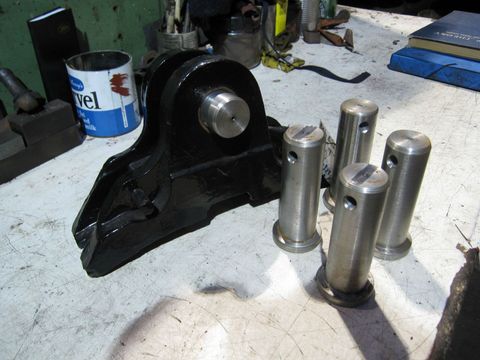
18th February 2016
As always the machining of new parts continues, twelve new pins have been made for the tender brake block holders. The photo shows four of the pins, with a fifth fitted into a brake block holder. All of the pins will be sent for case hardening shortly.
Images on this page are copyright A.J.Morgan, M.Playle, G.Briggs