Boscastle Locomotive Limited
25th November 2016
Boscastle Firebox Stays
Report by Mike Playle
So as to give South Devon Railway Engineering no reason to slip our project down the ever growing queue of Bulleid boilers, I am mindful that we have to get our boiler to them within a reasonable timescale.
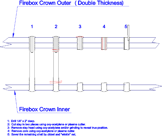
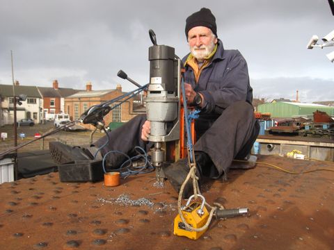
Consequently I have attempted to spend two or three days a week gnawing away at the daunting task of severing and removing 1,800 (or is it 2,000?) firebox stays. The focus of my recent attention has been the firebox Crown (top) with stays laid out in an approximate matrix 21 x 14. My efforts have centred on drilling each stay, from the outside, as the first stage in the laborious process of removal. The diagram below shows the steps required from 1 to 5.
There are pros and cons to working on the crown...
Pros :
- Gravity assists in applying feed force to the drill (as opposed to having to push upwards).
- Except for near the outer row the firebox surface is relatively flat (but see the mention of riveted heads in cons) thus there is a prospect of using a magnetic base drill.
- Swarf does not fall back onto me.
- I get a good view of what is going on around the shed.
Cons:
- Fetching and fixing a heavy ladder each day then rolling back a cumbersome cover.
- Rivets prevent the drill mag base touching down. Consequently it does not get a grip anywhere near enough to resist the necessary drill feed force and requires some “work arounds”.
- The height can be vertigo inducing and means that all movements of equipment and person must be considered. I have been carefully tethering the drill when working on the outer four rows.
- Being constrained to one sitting position for hours on end leads to stiff and aching joints. Descending the ladder can be an effort after a long session.
- Exposure to weather can be an issue.
- Lifting and lowering the big drill to 10 ft up requires a person in good physical shape (to supplement the feeble old codger up top).
- The crown is reinforced over half its area by addition of a second thickness of plate. This is riveted, which adds to the clutter of rivet heads and further obstructs the drill mag base. More significant is that any drilling has to allow for the extra thickness and then go some way beyond. The drilling depth is therefore around 2 inches, which is a lot of metal to shift. This is compounded in that the drill flutes start to choke beyond 1.5”. Consequently the drill has to be frequently withdrawn to clear the swarf and avoid drill breakage. Even where the crown is not doubled the edge of the second plate will impede the subsequent flame cutting process so even those stays in singular thickness need to be drilled near to the same depth.
The “work arounds” mentioned are aimed at getting the mag base drill to remain stable.
To get the magnet to do anything requires a magnetic link between the flat plate surface and the magnet with up to four or five riveted heads in the way. Simple bits of plate would not work as they would simply short out the magnetic field. These plates would attach to the magnet but would not be interested in the firebox surface.
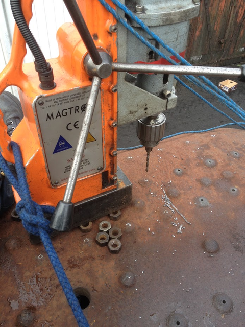
What has been used is a pile of 3/4” nuts. These are too small to short out the magnet but provide discrete paths to direct the magnetic flux down to the boiler plate so some grip is achieved. Unfortunately this remnant magnetic grip, while enough to stop the drill skating about, is not enough to provide the feed force. We have thus established a technique using rope stays to strategically placed anchor points.
The anchor points can be a fixed stud, a lifting magnet, a tapered plug, an old firebox stay replaced in a vacated stay hole. The stays, pre tensioned, hold the front of the machine down sufficient for the drill to generate nice curly swarf. This prevents the drill rubbing and results in long drill life. One drill has cut around 150 holes without sharpening. The staying arrangement has evolved with time and now includes some pulleys out of my chandlery box, spin-off from my sailing interest.
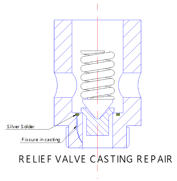
Relief Valve Repair
The Summer Report carried a photograph of a cylinder relief valve being set (hydraulically) at the stipulated 275 psi to protect the cylinders from over-pressure.
One of the six valves was very difficult to set in that pressure decayed rapidly before the set point was approached. The seat was examined microscopically and a small flaw repaired with lead free solder. Still the valve did not behave correctly. Grinding the poppet against the seat did not result in improvement.
The valve was trial assembled with the spring and the setting screw (not shown in the picture) replaced by a length of bar held in place with G cramps so that the inside of the housing could be seen through the opening. When the underside was pressurised with water a series of jets issued from the bottom internal face indicating that the cast body contained a flaw running right through. Having been revealed in this way it was evident that the exit side of the flaw was visible on the turned internal face as a clear circumferential line. The inlet end of the flaw was searched for but was not clearly evident and the picture is conjectural as far as the inlet is concerned.
The valve body came home with me and a groove was turned on the inner face coinciding with the visible trace. Back at Loughborough the body was set up on a gas ring in the white metalling bay with a ring of pre-fluxed silver solder in the groove. With a bit of extra heat from a propane torch the solder melted and flowed nicely into the groove.
The body was boiled in water to soften the remnant flux, cleaned, then the innards re-fitted and relief pressure set without any issue. This exercise has saved us the cost of a replacement casting!
14th October 2016
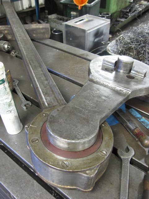
In this view the left hand return crank and return crank rod have been reassembled. The return cranks are the only parts on the loco that have a ball bearing fitted, the rod and the crank are a press fit together, which then has a large nut to fasten them and a pin through the nut as additional security. The rear of the crank is shown, with the new leather seal fitted.
2nd November 2016
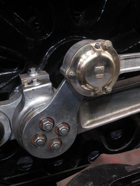
The right hand return crank and return crank rod have also been put back together and both sets fitted to the loco. This shows the right hand set with the highly polished brass bearing cover fitted. The sharp eyed reader will note that the lettering on the cover is up side down, this is the way the casting has been made and cannot be rotated to correct this, so in short we've not put it on the wrong way round!
25th October 2016
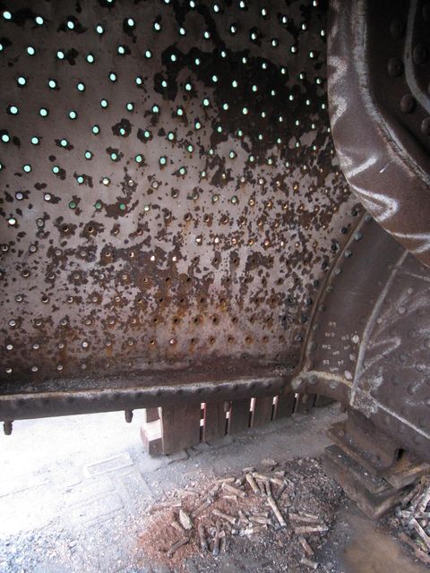
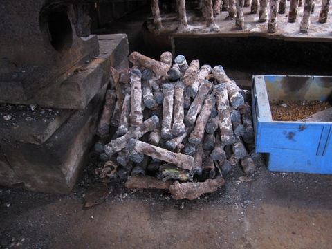
Work on the firebox continues, with a large part of the inner left hand firebox side removed previously, the remaining stays above the cut area are accessible. These have been cut from between the plates with an Oxy Acetylene cutting torch for the steel stays and plasma cutter for the monel stays. The picture shows a pile of cut says and debris on the floor.
25th October 2016
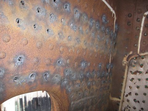
This shows the rear inner firebox door plate. The stays are being removed by burning the riveted ends out of the plate so that the remaining stay stub can be drilled and punched free from the outside. This reduces the amount of time taken to free them all as drilling is a slow and laborious process, any damage caused by the burning process doesn't matter, because the inner firebox is scrap. We are however trying to remove the stay ends as cleanly as possible so that we can use the hole positions for reference if need be when marking out the new inner firebox.
25th October 2016
This shows a pile of cut stays, we have three buckets full of these at present with many more to come. The few very brown corroded lumps amongst the pile are stays removed during its last repairs in the 1990's which got stuck in the firebox and couldn't be removed.
26th October 2016
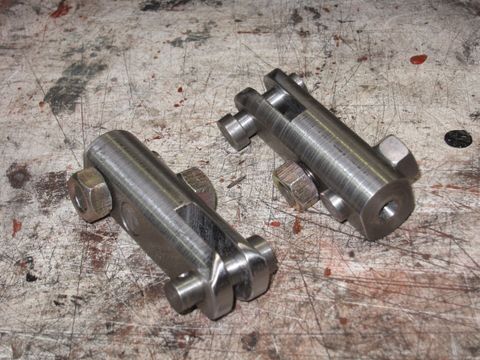
Our machinist keeps turning out some lovely work, these are two whistle pull cable clamps. We had two originals to copy and quite a bit of work went into these small items. We now have a complete set which should hold the cable correctly and reduce the chance of it fraying and snapping when the whistle is pulled by some of the more heavy handed crews.
16th November 2016
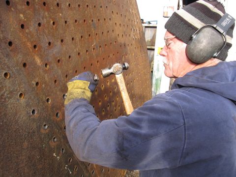
This shows occasional Boscastle volunteer and itinerant stay remover David Mathews shelling out stay remains on the left hand outer firebox side. Once the stays have been drilled and punched out, the remaining thin piece of stay end left behind has to be cleaned out to reveal the threaded hole in the plate. David finds drilling and removing stays very satisfying - takes all sorts! nevertheless, we're very grateful for his contribution.
18th November 2016
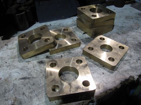
Eight new injector steam pipe flange castings have been turned, milled and drilled to produce the fine collection of metalwork shown. These are the last components to be machined for the injectors and are to hand for when we produce the revised pipework to the correct arrangement, most of which can't be done until the boiler is fitted to the loco.
Images on this page are copyright A.J.Morgan, M.Playle