Boscastle Locomotive Limited
28 May 2016
Coupling and Connecting Rods
Andy and his team have made great progress on the locomotive in recent months, not least of which with the fitting of Boscastle's Coupling and Connecting rods. The following images document their progress:

Here, the right trailing coupling rod is being trial fitted. Each coupling rod section is lifted on the lift truck and slid into position on its crank pin, which has been smeared with marking blue. The rod is then removed, and any tight spots on the bearing identified by the marking blue are scraped off.
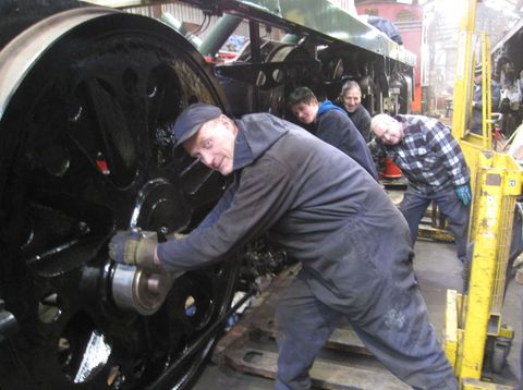
Following the trial fitting, Rob Stinchcombe (GCR), James Morgan, Keith Devereux and Malcolm Prosser pushed the left-hand coupling rods into position. Rob was on hand to give the Boscastle team help and guidance as he has experience of fitting these parts.
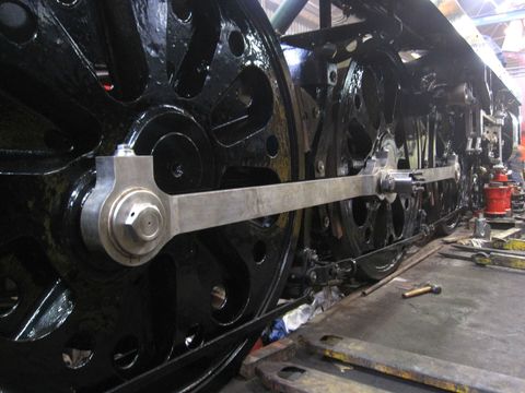
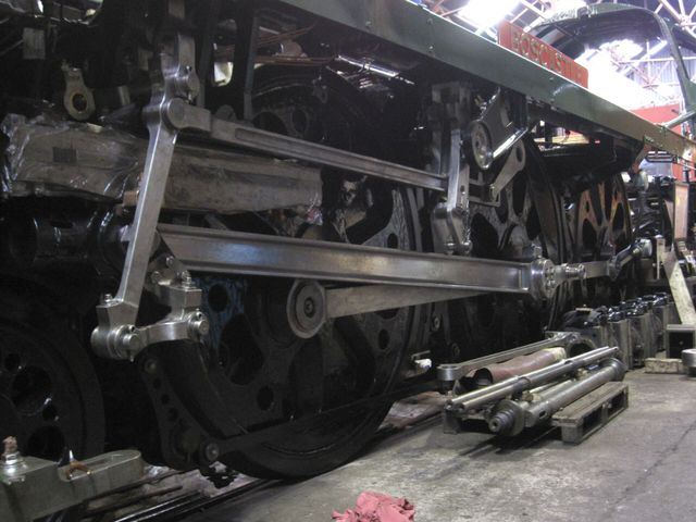
Both sets of coupling rods are now fitted. With a few adjustments to the position of the wheels, they all slid on perfectly with a minimum of fuss. This photo shows the right-hand set in position.

This shows the left hand connecting rod having the small end bearing machined to its final size on the horizontal borer. This gives some idea of the size of these parts, with the big end hanging over the lathe on the opposite side of the machine shop, eleven feet away!
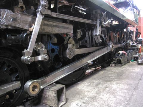
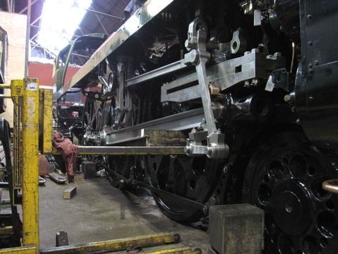
This shows the left-hand con rod being trial fitted using the same method as for the coupling rods. Because of the high standard of machining and the finishes achieved, little remedial work has been required to any of the bearings.
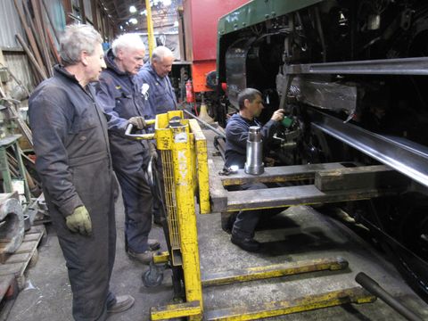
The gang look on as Craig Stinchcombe prepares to fit the gudgeon pin (seen sitting on the lift truck) which joins the small end of the con rod to the crosshead.
This shows the left-hand con rod finally fitted to the locomotive. The right hand rod will require much of the stored parts, the bench and all of the cupboards behind the loco to be moved so that it can be moved backwards. There is no alternative as the gudgeon pin can only be inserted in one place.
26th February 2016
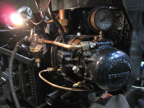
Due to poor lighting and a heavy demand on the shed's air supply, we were unable to get a photo of the Stones generator being tested in the last newsletter. This photo shows the generator running with a light bulb glowing brightly on the electricity being generated.
12th May 2016
Now that the weather has improved, we have been out drilling stays on the boiler again. This shows the throatplate (front of the firebox) in the process of being drilled and demonstrates the process. The silvery ones have been ground flat and marked for drilling, the ones on the lower right have been pilot drilled and the stays on the left have been drilled twice and will be drilled at least once more.

13th May 2016
The machining of small parts continues, new gland nuts for the injector steam and water valves have been made. These are part of the sealing arrangement that prevents steam or water escaping past the valve spindles

12th May 2016
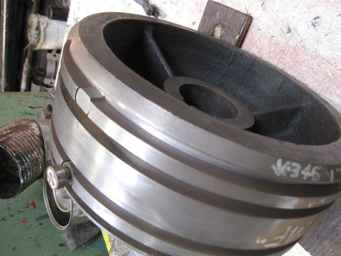
This shows one of the middle cylinder piston valve heads with all of the stops for the valve rings fitted. The lower one still has the sacrificial top piece on, which is used to screw the part in and is then sawn off. The upper stop is finished, the top piece has been removed and the sides filed flat. All of the valve heads are now finished.
19th May 2016
This shows the right hand con rod fitted. The small end has just been lifted on the pallet truck and the small end (Gudgeon) pin inserted. To fit this rod, the whole loco had to be moved back six feet. It took about two hours to fit, ten minutes to move the loco back to its usual position and three of us a whole day to put all the equipment back!
13th May 2016
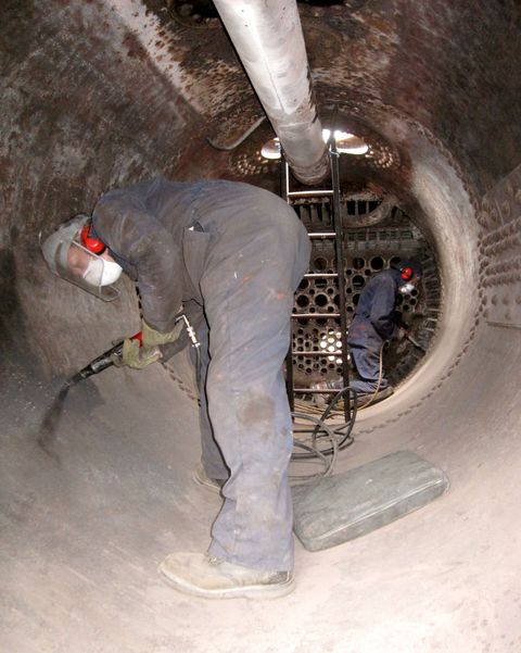
This shows Malcolm and Nigel needle-gunning the inside of the boiler barrel to remove limescale, they have been doing this for several months and are nearly finished. Everyone will be pleased when this horrendously noisy job is complete, all though some have begun to suspect that they both quite like it now!
Images on this page are copyright A.J.Morgan