Boscastle Locomotive Limited
22nd May 2015
Expansion links - the outside links
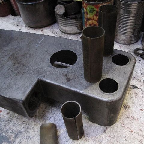
News that the outer sets had been received back from the contractor with new holes formed by wire erosion just made it to us in time for the last newsletter. Each pair was returned, still with the temporary bolts holding the two halves in the correct position. Also returned were the thin annuli which fell out as a result of cutting the (originally 1”) bolt holes at 1.1” diameter. Visible eccentricity of these annular off-cuts, pictured below, confirmed the need for re-shaping these holes.
The wire erosion process has guaranteed that:
- All four bolt holes match (which they did not previously)
- The curved tracks are optimally positioned relative to the main pivots (on which the links oscillate)
- The pivot holes which receive the drive from the link from the eccentric are parallel to the main pivots (and hence axis of oscillation)
While the reshaped holes are remarkably accurate considering that they have been cut with a taut wire, we did find some striations and high points which resulted in seizure of a fitted bolt during early fitting. As a consequence, some time has been taken to dress out these high points with emery flap wheels and to get the holes to near-perfect circularity.
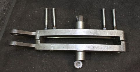
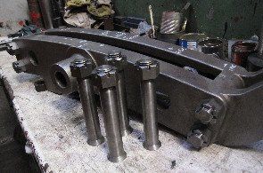
The photo shows one of the sets with its newly fitted bolts withdrawn for the picture. These have been turned in-house to individually match holes to less than a thousandth of an inch accuracy.
The same process has been applied for the actuating pivot pins (the holes for which are to the left of the picture) which will now be hardened. The bronze blocks, which slide in the curved tracks, are still to be completed.
The inside links
Boscastle being a three cylinder locomotive, we have outstanding the problem of how to deal with the inside set of links where one of the halves is fractured.
Enquiries to locate a spare set have so far led nowhere. Making a new set by the original route of forging and carburising is very expensive and carries the risk of repeating the distortion seen in the originals (and from which all this extra work stems).
As a consequence, I have been investigating alternative manufacturing routes which have included options such as machining from solid and different surface hardening processes. A breakthrough came when Andy Morgan heard that the Patriot Locomotive project had investigated cast, in place of forged, links. A telephone call to their draughtsman revealed the identity of the pattern maker who has subsequently quoted us for casting in a very tough alloy, which brings with it suitability for nitriding as the surface treatment rather than the risky carburising of our low carbon steel originals. We are led to understand that the Vehicle Acceptance Body for the Patriot has deemed their process acceptable for a main line locomotive. This gives confidence for us to explore this route further and make our own submission to a VAB for cast items.
Gas Nitriding is a process where the part is exposed to an ammonia atmosphere at a moderate temperature of 550 degrees Celsius. Alloys within the steel combine with nitrogen in the ammonia to form very hard nitrides. The process penetrates deeper, to a sensible maximum of about half a millimetre. Provided the part has seen a stress relieving heat cycle just above this temperature, prior to final machining, the risk of distortion is very low. Another advantage of this low process temperature is that the underlying (En19) core of the component will not lose its “temper” and can be cast at condition “T” and remain there. Steel at condition “T” is machinable but has much higher tensile strength than the core material of our existing links. Thus any new part made via this route should be much stronger than the originals.
Nitriding is commonly used for crankshafts, camshafts and gears where a hard surface on a tough core is needed. I have personally used the process to create hard tips on a cutter for sampling graphite.
An expansion link on Standard 2MT 78019 which is very similar to those on Boscastle. The curved expansion link is supported in the large black bracket, while the radius rod passes through the expansion link.
The radius rod is raised and lowered in the expansion link by the weigh shaft arm, half of which can be seen in the centre of the right-hand side of the photograph. In this image the locomotive is in ‘mid-gear’ (neutral in motoring terms!) with the radius rod set through the centre of the expansion link.
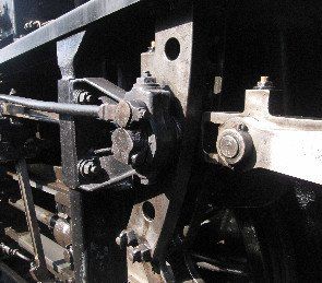
Here the radius rod has been lowered, which puts the locomotive in full forward gear. To reverse the locomotive, the radius rod is lifted above the centre position in the expansion link, up to the top.
The curve in the expansion link gives maximum movement of the radius rod in the top and bottom positions while reducing movement as the rod is moved toward the middle (mid-gear). By setting the radius rod at the intermediate positions the efficiency of the locomotive becomes increased.
On Boscastle, the forward and reverse positions are opposite to this, with forward gear being at the top and reverse at the bottom.

28th April 2015
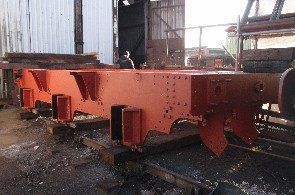
This shows the tender frames, which our volunteers have thoroughly cleaned and then painted with two coats of red oxide primer. The frames are in generally good condition but the front dragbox (the point at which the engine and tender are connected) has corroded to the point where it will need to be replaced.
29th April 2015
The new fitted bolts and castellated nuts for the outside expansion links have been machined and trial fitted. The photo shows four of the pins, which are a very precise fit and tailored to their respective holes (hence ‘fitted’). All have been trial fitted and four more can be seen in position in the expansion link behind.
29th April 2015
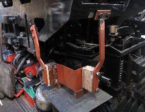
The new injector brackets are being trial fitted. The photo shows the brackets mounted under the rear of the cab, the wooden blocks represent the injector mountings and save having to lift these heavy fittings up and down while adjustments are made. Once we are happy with the positions, bolt holes can be finalised and the injectors fitted.
29th April 2015
This shows some of the tender rear marker lights, all of which have been cleaned and repainted, white on the inside and BR green on the outside. The re-furbished bulb holders and switches can now be refitted.

Images on this page are copyright A.J.Morgan, M.Playle